ElectronsX > Supply Chains > EV Supply Chain > Power Electronics & HV/LV Electrical Stack
Power Electronics & HV/LV Stack
Power electronics are the active semiconductor-based systems that convert, control, and condition electrical power - and they are the highest-convergence supply chain node in the entire electrification ecosystem. The same SiC power modules produced by Wolfspeed, Infineon, STMicro, and Onsemi are simultaneously demanded by EV traction inverters, BESS power conversion systems, EVSE DCFC cabinets, solar inverters, wind turbine converters, industrial VFDs, datacenter UPS systems, and robot joint drives. No other component touches this many sectors at once. See: SiC & GaN - The Universal Power Substrate
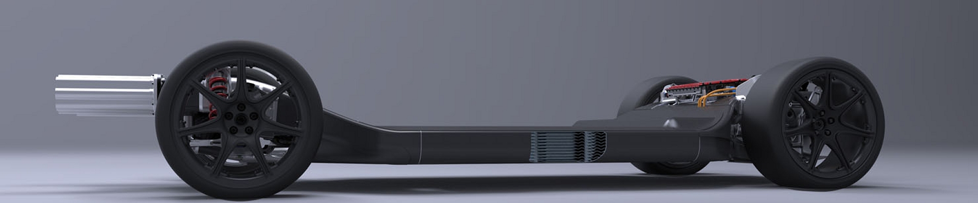
In the EV context, this node covers the full power-distribution backbone: how energy flows from the traction battery through high-voltage components into the motor or e-axle, DC fast-charging interface, and onboard charger, and how it is stepped down into low-voltage domains that run controls, safety, ADAS, connectivity, and comfort systems.
This node covers two distinct but tightly coupled layers. The active conversion layer - traction inverters, OBC, DC-DC converters, and power control units - is where SiC and GaN semiconductors define efficiency, power density, and voltage architecture. The passive distribution layer - HV busbars, junction boxes, contactors, wiring harnesses, LV PDUs, and zonal controllers - is where harness complexity, wiring labor concentration, and connector supply create separate but equally significant supply chain risk.
The defining technology transitions are: SiC MOSFET replacing IGBT in traction inverters (enabling 800V platforms and faster charging), GaN emerging in OBC and LV conversion stages (enabling compact high-frequency magnetics), and the shift from distributed ECU architectures to zonal controller architectures (reducing harness weight and enabling software-defined vehicle functions).
Position in the EV Stack
| Layer | Typical Voltage | Primary Role | Key Components |
|---|---|---|---|
| High-Voltage (HV) | 400-800V DC (next-gen platforms higher) | Traction power, DC fast charging, high-power auxiliaries | HV battery, contactors, busbars, traction inverters, OBC, HV DC-DC, DCFC interface |
| Low-Voltage (LV) | 12V / 24V / 48V | Controls, safety, sensing, communications, comfort | LV battery, PDUs, VCUs, zonal/domain controllers, actuators, infotainment, telematics |
Upstream from this node: Battery packs/modules, motors/e-axles, power semiconductor dies (SiC/GaN/IGBT) - see Battery SC, Motor SC, and SemiconductorX
Downstream from this node: Propulsion output, ADAS/AV compute, body/zonal systems, thermal loops, charging interfaces, V2X functions
Core Power Electronics Assemblies
| Assembly | Function | Semiconductor | Key Trends |
|---|---|---|---|
| Traction Inverter | Converts HV DC battery power to 3-phase AC for traction motor; controls speed and torque via PWM switching | SiC MOSFET (premium/mainstream); IGBT (cost-sensitive/legacy) | SiC enabling 800V; higher switching frequency; smaller cooling; integration into PCU with OBC and DC-DC |
| Onboard Charger (OBC) | Converts AC grid or depot power to HV DC for battery; implements PFC, isolation, and EVSE communication | GaN emerging for switching stage; SiC for higher-power units | GaN enabling compact magnetics; bidirectional V2G/V2H emerging; integration with DC-DC into PCU |
| DC-DC Converter | Steps HV bus (400/800V) down to LV rails (12V/24V/48V) for vehicle electronics; eliminates belt-driven accessories | GaN for isolation stage; SiC for high-voltage primary side | Multiple isolated outputs; bidirectional designs emerging; stable LV under transient HV events |
| Power Control Unit (PCU) | Integrates inverter, DC-DC, and sometimes OBC into one thermal and packaging assembly near motor/e-axle | SiC MOSFET dominant in integrated PCU designs | Co-location for thermal efficiency; hosts highest-value power semiconductors; includes motor control logic |
| Bidirectional Charger (V2G/V2H) | Enables power flow from EV battery to grid or home; combines OBC and inverter functionality | SiC required for bidirectional efficiency at grid frequency | Fleet V2G becoming commercial; utility-grade isolation and protection required |
High-Voltage System
The HV domain carries the bulk of traction and charging power. It is defined by safety, insulation, creepage and clearance, and the ability to handle high currents and switching events without undue losses or EMI. HV architectures are either 400V DC or 800V DC for current platforms, with higher voltages emerging in next-generation truck and industrial platforms.
Key engineering themes: thermal behavior under sustained load, switching losses and efficiency, EMC/EMI compliance, creepage/clearance, insulation coordination, and robust fault detection under both drive and charging conditions.
Key HV components beyond the active converters: main contactors and pre-charge circuits, isolation monitoring devices (IMD), HV busbars and cables, HV junction boxes and service disconnects, HV connectors (HVILs, manual service plugs), and pyrofuses for crash isolation.
HV & LV Wiring Harness Systems
HVIL Interlock - High Voltage Safety
Safety & Redundancy Hardware
Low-Voltage System
The LV domain supports vehicle control, safety, sensing, communications, and comfort. It also powers high-performance compute for ADAS and autonomy, either directly or via intermediate rails. Traditional 12V architectures are gradually giving way to 24V and 48V systems on advanced platforms. Designing a robust LV domain requires maintaining stable supply rails under dynamic load conditions, separating critical from non-critical loads, and supporting future growth in compute and sensor power without excessive harness complexity or weight.
Modern EVs increasingly rely on LV-powered chassis actuators that go well beyond traditional steering or damping: active suspension, torque-vectoring axle actuators, rear-wheel steering (4WS), steer-by-wire, crabwalk mechanisms, and active aero surfaces. These draw from 12V, 24V, or 48V rails and are orchestrated by zonal controllers or dedicated chassis control units - consuming data from propulsion, braking, and ADAS road-preview systems, making them tightly integrated into the broader vehicle control architecture.
Power Semiconductor Devices
The HV/LV electrical stack is where most high-value power semiconductor devices are deployed, bridging upstream semiconductor supply chains and downstream vehicle platforms.
| Device Type | Typical Use | Advantages | Tradeoffs |
|---|---|---|---|
| SiC MOSFET | Traction inverters, HV DC-DC, DC fast-charging stages | High efficiency, high voltage and temperature capability, smaller cooling requirements | Higher device cost, evolving substrate and wafer supply, 52+ week lead times |
| IGBT / Si MOSFET | Cost-sensitive inverters, mid-power converters, legacy platforms | Mature, lower device cost, widely available tooling and qualification | Higher switching losses, lower efficiency at higher voltages and switching frequencies |
| GaN HEMT | Onboard chargers, LV converters, high-frequency stages, robot joint drives | Very high switching speed, compact magnetics, high power density | Automotive ecosystem still maturing, voltage rating limits for traction |
Upstream semiconductor supply chain (wafer, epitaxy, fab, packaging) is covered on SemiconductorX. The highest-convergence supply chain story is here: SiC & GaN - The Universal Power Substrate
Controllers & Vehicle Architecture
Control units orchestrate both HV and LV systems, consolidating functions and enabling software-defined vehicle behavior. The shift from distributed ECU architecture to zonal controller architecture is the defining LV supply chain transition of 2024-2030 - reducing harness length and weight while enabling faster OTA updates and centralized compute.
VCU (Vehicle Control Unit) - central intelligence for propulsion, torque management, regenerative braking, and safety interlocks
PCU/MCU (Power/Motor Control) - manages inverter operation, motor torque and speed, and associated protections
BMS/BCU (Battery/Control Unit) - supervises HV safety, contactors, SOC/SOH estimation, cell balancing, and diagnostics
Gateway ECU - bridges CAN, LIN, Ethernet networks; enforces cybersecurity, firewalling, and OTA pathways
Zonal Controllers - next-generation LV nodes consolidating multiple ECUs per zone, reducing harness complexity
BCM (Body Control Module) - legacy LV controller; functions migrating to zonal architecture on modern platforms
See: Central Compute & Control Overview | SDV Systems Supply Chain | Software-Defined Vehicles
Cross-Sector Deployment - SiC/GaN Convergence Map
Power electronics is the highest-convergence supply chain node in the entire electrification ecosystem. The same SiC power modules produced by Wolfspeed, Infineon, STMicro, and Onsemi are simultaneously demanded by EV traction inverters, BESS power conversion systems, EVSE DCFC cabinets, solar string inverters, wind turbine full-power converters, industrial VFDs, datacenter UPS systems, and robot joint drives. No other component in the electrification supply chain touches this many sectors at once - and the compound demand shock across all nine has driven SiC lead times above 52 weeks at peak and will continue to pressure supply through 2027. This cross-sector mapping is one of EX's core editorial moats.
| Sector | Application | SiC/GaN Role | Demand Trajectory |
|---|---|---|---|
| EV Traction | Traction inverters, OBC, DC-DC converters | SiC MOSFET replacing IGBT across premium and mainstream segments; enabling 800V | Very High - 800V platform rollout accelerating SiC content per vehicle |
| BESS / Grid Storage | Power conversion systems (PCS), grid-tie inverters | SiC in high-power PCS for Megapack, EnergyOne, Fluence Gridstack | Very High - utility BESS capacity scaling globally at record pace |
| EV Charging (EVSE) | DCFC power modules, MCS charger stages, V4 Supercharger | SiC enables 150-500 kW charging with high efficiency in compact cabinets | High - V4 Supercharger and MCS rollout driving sustained demand |
| Solar Inverters | String inverters, central inverters, microinverters | SiC and GaN both used; higher frequency enables smaller magnetic components | High - utility solar scale-up driving string inverter volumes |
| Wind Turbine Converters | Full-power and partial-power converters for MW-scale turbines | SiC enabling higher efficiency and reduced cooling in multi-MW full-power converters | Medium-High - offshore wind scale-up driving large-format SiC module demand |
| Grid Infrastructure | STATCOM, flexible AC transmission, solid-state transformers | SiC enabling higher switching frequency and efficiency in grid power electronics | Medium-High - grid modernization program expanding globally |
| Industrial Motor Drives (VFDs) | Variable frequency drives for pumps, compressors, fans, conveyors | SiC replacing IGBT in premium VFDs; GaN in fractional-kW drives | High - massive installed base; SiC adoption in new designs accelerating |
| Datacenter UPS & PSU | Uninterruptible power supplies, server PSUs, AI training cluster power | GaN dominant in high-efficiency PSU; SiC in large UPS and backup systems | Very High - AI training cluster buildout creating new high-volume GaN demand signal |
| Robot Actuators | GaN joint drive inverters, servo motor controllers in humanoid and quadruped robots | GaN enables compact high-frequency drives for robot joints at low voltage | Emerging - humanoid scale-up creates new GaN demand curve post-2026 |
See: SiC & GaN - The Universal Power Substrate | Supply Chain Convergence Map
Grid-Forming Inverters — Physics Emulation Under Software Control
The most precise illustration of what power electronics actually do is the grid-forming inverter. Traditional grid-connected inverters are grid-following — they lock to an existing grid signal and inject power in synchrony with it. Grid-forming inverters do something fundamentally different: they synthesize a voltage waveform from scratch, running control algorithms that emulate the electromagnetic behavior of a rotating synchronous machine — inertia, frequency droop response, voltage support — entirely in software, with no moving parts.
As coal and gas plants retire, they remove decades of accumulated rotational inertia from the grid. Grid-forming inverters replace that inertia synthetically — using SiC switching speeds fast enough that the emulated waveform is electrically indistinguishable from a real machine's output. This is not switching. This is physics emulation under software control. It is the clearest possible demonstration that power electronics are programmable energy transformation nodes, not passive components.
Grid-forming capability is now required or incentivized by grid codes in the UK, Australia, Ireland, and increasingly the US. Every utility-scale BESS, every large solar farm, and every islanded microgrid that must provide grid stability is a potential grid-forming inverter deployment — all drawing from the same SiC supply chain as the EV traction inverter in the vehicle in your driveway.
400V vs 800V Architecture
The shift from 400V to 800V battery architecture is the largest single driver of SiC adoption in EV power electronics. At 800V, current is halved for the same power (enabling thinner cables and smaller connectors), switching losses are lower, and charging power can scale to 350 kW+ without impractical cable sizes. SiC is required for 800V - silicon IGBT cannot switch efficiently at these voltages within automotive thermal envelopes.
800V platforms in production or imminent: Hyundai/Kia E-GMP (Ioniq 5/6, EV6/9), Porsche/Audi PPE, Lucid Air, Tesla Cybertruck, BMW Neue Klasse, Mercedes AMG.EA. The 400V segment remains dominant by volume but 800V is the architecture of record for new premium platform development.
See: EV Platforms & Architecture Hub | Hyundai E-GMP
Interfaces with Other EV Systems
Battery SC: Pack voltage, current limits, thermal constraints, and safety envelopes define the HV/LV stack operating envelope. See: Battery Supply Chain
Motor & Drivetrain: Inverters and e-axles are co-designed for efficiency, torque delivery, and thermal behavior across drive cycles. See: Motor & Drivetrain SC
ADAS & Autonomy: HV/LV architecture must support high-power compute, redundant sensor power, and low-noise rails. See: SDV Systems SC
Charging & Infrastructure: Stack connects to depot charging, DC fast charging, and V2G/V2D power flows. See: EVSE & Depot SC
Thermal Systems: Power electronics, battery, and motors often share cooling circuits - electrical and thermal architectures are tightly coupled. See: Thermal SC
Related Coverage
HV/LV Electrical Systems: HV & LV Wiring Harness | HVIL Interlock | Safety & Redundancy Hardware | AC-DC Rectifiers | AC-AC Converters
Semiconductors: SiC & GaN Universal Substrate | Convergence Map
Cross-Sector: BESS Supply Chain | EVSE & Depot SC | Robot Actuator Power Electronics
EV Supply Chain Peers: Battery SC | Motor & Drivetrain SC | Thermal SC | Networking & Comms | SDV Systems SC
Parent Nodes: EV Supply Chain Hub | Supply Chains Hub